Visualize
Extended Parameters
View > Camera > Properties > Draft > Rendering Type : Visualize > Rendering Mode : Visual Style - X-Ray
( Shortcut : Right-click in the editor > Right-click on Draft Render > Set the Render Type to Visualize and the Render Mode to Render Style - X-Ray)
- The Extended Parameters below are available using the following Visual Styles :
- X-Ray
- Conceptual
- Shades of Gray
- Realistic
- Shaded
- Sketchy
In the examples below, the Visual Style - X-Ray is used to demonstrate this technique
Edge Model
The edges, contours and isolines of the model can be controlled so that the following elements are displayed :
No Edges
This produces a rendered image with transparent edges and surfaces.
Worked Example
- Draw a 3D object of your choice or download the sample here.
- Right-click in the editor, then right-click on the Draft Rendering tool.
- Set the Rendering Type to Visualize.
- Set the Rendering Mode to Visual Style : X-Ray.
- Set the Edge Model to No Edges.

Isolines
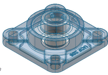
This produces a rendered image showing shaded isolines which connect contours. The isolines can be rendered in a different color to the model. In the example below, the edge model Isolines is selected and the color is set to Steel Blue. The Edge Opacity is set to 100% and the Face Opacity is set to 30%.
Worked Example
- Draw a 3D object of your choice or download the sample here.
- Right-click in the editor, then right-click on the Draft Rendering tool.
- Set the Rendering Type to Visualize.
- Set the Rendering Mode to Visual Style : X-Ray.
- Set the Edge Model to Isolines.
Facet Edges
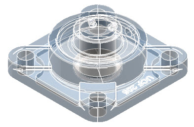
This produces a rendered image showing shaded edges, leaving the model with transparent surfaces. The isolines canbe rendered in a different color to the model. In the example below, the edge model Isolines is selected and the color is set to White. The Edge Opacity is set to 100% and the Face Opacity is set to 30%.
Worked Example
- Draw a 3D object of your choice or download the sample here.
- Right-click in the editor, then right-click on the Draft Rendering tool.
- Set the Rendering Type to Visualize.
- Set the Rendering Mode to Visual Style : X-Ray.
- Set the Edge Model to Facet Edges.
Edge Color
A contrasting edge color can be provided using the following edge models :
- Isolines
- Facet Edges
This is used for rendering purposes only and does not change the outline color of the model.
Worked Example
- Draw a 3D object of your choice or download the sample here.
- Right-click in the editor, then right-click on the Draft Rendering tool.
- Set the Rendering Type to Visualize.
- Set the Rendering Mode to Visual Style : X-Ray.
- Set the Edge Model to Isolines or Facet Edges.
- Select on the Edge Color selection bar and select the color from the color properties blocks.
Edge / Face Opacity
The degree of edge opacity determines the transparency of the edge or faces color when using the following edge models :
- Isolines
- Facet Edges
In the example below, the degree of Face Opacity is set to 70% using the Facet Edges model. The edge color is set to white.

Worked Example
- Draw a 3D object of your choice or download the sample here.
- Right-click in the editor, then right-click on the Draft Rendering tool.
- Set the Rendering Type to Visualize.
- Set the Rendering Mode to Visual Style : X-Ray.
- Set the Edge Model to Isolines or Facet Edges.
- Select the degree of Edge Opacity to the preferred value.
0% represents total transparency and 100% represents total opacity.
Edge Crease Angle
This feature determines the degree of sharpness or smoothness of adjacent faces along an edge. The range of the Edge Crease Angle is 0-180 degrees, increasing in sharpness towards 180 degrees.
In the example below, two examples are shown. The left image shows an Edge Crease Angle of 0 degrees; the right image shows an Edge Crease Angle of 90 degrees.

Worked Example
- Draw a 3D object of your choice or download the sample here.
- Right-click in the editor, then right-click on the Draft Rendering tool.
- Set the Rendering Type to Visualize.
- Set the Rendering Mode to Visual Style : X-Ray.
- Set the Edge Model to Facet Edges.
- Set the degree of Edge Crease Angle to the preferred value.
Silhouette
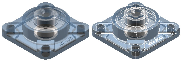
The Silhouette edge style emphasizes the edges of the model and represents them as bold, contrasting lines. In the examples below, the Silhouette Edge is disabled on the left and enabled on the right.
The Silhouette edge style can be applied when using the following edge models :
- No Edges
- Isolines
- Facet Edges
Worked Example
- Draw a 3D object of your choice or download the sample here.
- Right-click in the editor, then right-click on the Draft Rendering tool.
- Set the Rendering Type to Visualize.
- Set the Rendering Mode to Visual Style : X-Ray.
- Set the Edge Model to Isolines or Facet Edges.
- Activate or Deactivate the Silhouette Edge style to achieve the required result.
Intersection
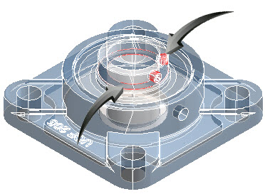
When the Intersection edge style is activated, all areas where there are intersecting solids are highlighted in a contrasting color.
The Intersection Edge Style applies only to objects rendered using the Facet Edges edge model.
In the example below, an edge color of red is selected. This indicates where intersecting solids occur.
Worked Example
- Draw a 3D object of your choice or download the sample here.
- Right-click in the editor, then right-click on the Draft Rendering tool.
- Set the Rendering Type to Visualize.
- Set the Rendering Mode to Visual Style : X-Ray.
- Set the Edge Model to Facet Edges.
- Activate the Intersection Edge Style.
- Select Options.
- Select the color and pattern from the properties dialog.
Intersection Color
The color of the intersecting edge can set to the preferred option when using the Edge Style : Intersection option.
- Draw a 3D object of your choice or download the sample here.
- Right-click in the editor, then right-click on the Draft Rendering tool.
- Set the Rendering Type to Visualize.
- Set the Rendering Mode to Visual Style : X-Ray.
- Set the Edge Model to Facet Edges.
- Activate the Intersection Edge Style.
- Select Options.
- Select the color from the properties dialog.

Intersection Pattern
The linestyle pattern of the intersecting edge can set to the preferred option when using the Edge Style : Intersection option.
- Draw a 3D object of your choice or download the sample here.
- Right-click in the editor, then right-click on the Draft Rendering tool.
- Set the Rendering Type to Visualize.
- Set the Rendering Mode to Visual Style : X-Ray.
- Set the Edge Model to Facet Edges.
- Activate the Intersection Edge Style.
- Select Options.
- Select the pattern from the dropdown options.

Face Color Mode
The Face Color option is available only when using the following options
- Edge Model : Facet Edges
- Edge Style : Intersection
See Also